Journal of the Mexican Chemical Society, vol. 65, no. 1, 2021
Sociedad Química de México A.C.
D. M. López-Rosas
Tecnológico Nacional de México - Instituto Tecnológico de Tijuana. Posgrado en Ciencias de la Ingeniería. C. P., 1166. Tijuana, B. C. 22000, México. , México
R. M. Félix-Navarro
Tecnológico Nacional de México - Instituto Tecnológico de Tijuana. Centro de Graduados e Investigación. C. P. 1166. Tijuana, B. C. 22000, México. , México
J. R. Flores-Hernández
Instituto Nacional de Electricidad y Energías Limpias, Ave. Reforma 113 Col. Palmira, Cuernavaca, Morelos, 62490, México. , México
C. Silva-Carrillo
Tecnológico Nacional de México - Instituto Tecnológico de Tijuana. Centro de Graduados e Investigación. C. P. 1166. Tijuana, B. C. 22000, México. , México
I. L. Albarrán-Sánchez
Instituto Nacional de Electricidad y Energías Limpias, Ave. Reforma 113 Col. Palmira, Cuernavaca, Morelos, 62490, México. , México
E.A. Reynoso-Soto *
Tecnológico Nacional de México - Instituto Tecnológico de Tijuana. Posgrado en Ciencias de la Ingeniería. C. P., 1166. Tijuana, B. C. 22000, México. , México
Tecnológico Nacional de México - Instituto Tecnológico de Tijuana. Centro de Graduados e Investigación. C. P. 1166. Tijuana, B. C. 22000, México. , México
Received: 16 July 2020
Accepted: 02 November 2020
Funding
Funding source: CONACyT
Funding source: SENER
Contract number: 292862
Contract number: 8080.20-P
Abstract: This work reports the synthesis, characterization, and catalytic activity of Pt-Ni/CNT with a low platinum load to use as cathode electrocatalyst in PEMFC (proton-exchange membrane fuel cells). The synthesis of nickel particles on the carbon nanotubes surface was carried out by chemical reduction of a Ni(ethylenediamine) complex; after that, the galvanic displacement reaction was performed to platinum deposition onto Ni/CNT. The Pt-Ni/CNT was deposited by spray technique on a gas diffuser layer (GDL) and subsequently subjected to several potential cycles to promote Ni atoms migration. Finally, its catalytic activity was evaluated in a fuel cell.
Keywords: Pt-Ni, PEMFC, potential cycles.
Resumen: En este trabajo, se reporta la síntesis, caracterización y evaluación catalítica del electrocatalizador Pt-Ni/CNT con bajo contenido de platino, empleado como electrocatalizador catódico en una celda de combustible tipo PEMFC (Celda de combustible de membrana de intercambio protónico). La síntesis de las partículas de níquel sobre la superficie de los nanotubos de carbono se llevó a cabo mediante la reducción química del complejo de Ni(etilendiamina) y posteriormente, se depositó platino sobre el material Ni/CNT mediante la reacción de desplazamiento galvánico. Se depositó una película de Pt-Ni/CNT sobre un difusor de gas mediante la técnica de esprayado y posteriormente fue sometido a diversos ciclos de potencial para promover la migración de los átomos de níquel y evaluar su actividad catalítica en una celda de combustible.
Palabras clave: Pt-Ni, PEMFC, ciclos de potencial.
Introduction
Nowadays, energy resources have begun to run out, which has generated an increased urgency to look for alternative fuels that are clean and renewable. A viable alternative for clean energy production is using the PEMFC. The PEMFC has attracted much more attention due to their high efficiency, high-power density, easy scale-up, and the lowest operating temperatures [1]. However, Pt catalysts' high cost stimulates interest in developing free or low-content platinum group metal catalysts to replace in PEMFC [2]. Diverse groups have conducted several investigations to enhance Pt catalysts' performance toward oxygen reduction reaction (ORR) in the cathode electrode, including its activity and durability in recent years [3,4]. One alternative to improve cathodic catalysts catalytic activity is supporting the Pt active phase over conductive materials; some of these materials employed are carbon nano-forms like; Vulcan carbon (C) [5], carbon black (NCB) [6], graphenes (GNPs) [7], multi-walled carbon nanotubes (CNT) [8], graphenes with intercalated carbon nanotube [9], graphenes with carbon black [10], and others. Pt electrocatalyst supported on multi-walled carbon nanotubes has diverse advantages compared with other carbon nano-forms for PEMFCs, generating excellent corrosion performance and higher stability in the ORR [11,12]. Further, other alternatives are employed using less Pt and maintaining excellent electrocatalytic performance incorporating a second metal. Numerous studies indicate that Pt and another metal's catalytic activity can enhance ORR [13,14]. Some examples of these bimetallic electrocatalysts are PtM3/C (M= Fe, Co, and Ni) [14], PtM /GNPs (M= Ni, Fe, and Cu) [7], Pt3M/NCB (M= Pd, Fe, and Ni) [6], among others.
The cathodic Pt-bimetallic catalyst catalytic activity improvement is the due to the changes in electronic properties, composition, structure, particle size, bond, and inter-particle distance. Various studies have proven the formation of Pt-layer over PtxMy catalyst's surface. PtxMy alloys with transition metals change the Pt surface energy, improving the catalytic activity in the ORR, promoting better O2 adsorption, and reducing the kinetics by a decrease in the Pt-Pt bond distance and a change of electronic structure by the increase of d-electron vacancies of Pt atom by the second metal content [15]. Gan et al. prepared PtxNi1-x, alloy catalysts and observed an increase in catalytic activity after the dissolution of Ni atoms by electrochemical potential cycles, by the increase in the Hupd area (an increase of electrochemically active area, ECSA) with the dissolution of the 50% of Ni atomic ratio of the catalyst composition, indicating the formation of Pt-layer in a catalyst surface [16]. Becknell et al. have prepared PtNi nanoframes. They observed an effect of Pt/Ni ratios over the ECSAs measured by CO stripping and H adsorption/desorption process, determining high catalytic activity in the ORR with 1.5 ratio and a decrease with 1.0 and fewer ratios [17].
Bimetallic catalyst based on Pt for the ORR has been prepared by diverse methods such as direct chemical reduction, electrodeposition, solvothermal, polyol, ligand coating, and galvanic displacement. These bimetallic catalysts for the ORR have been developed as alloys, dispersions, and core-shell particles. Core-shell catalysts are excellent in the ORR and generally are composed of non-noble transition metal as core and an active noble transition metal as the shell. The core physicochemical characteristic is critical for the distribution of noble metal atoms in the shell surface. The use of stabilizing agents or ligand may influence core-shell nanostructures growth, stability, and surface chemistry because the ligands play multiple roles in the synthesis of these type of particles, like improving the solubility of metallic precursors, as a diffusion barrier, change in the nucleophilicity of metal, stabilizing agent for Ostwald ripening or agglomeration, and as growth director [18]. Galvanic displacement is one of the most effective methods to prepare core-shell particles. The process combines aspects of corrosion and electrodeposition when the less noble metal with a specific physicochemical characteristic interacts with the noble metal ions; these will be reduced due to the difference in the metals redox potential depositing in the surface of non-noble transition metal [19].
Many authors report the synthesis of particles with core-shell structure by galvanic displacement as Pt bimetallic catalyst for the ORR and propose different strategies to improve the catalytic activity like the dealloying and leaching of less noble metal, by thermal treatment, chemical dissolution, or electrochemical process [20-22]. The dealloying and leaching of a core-shell structure can produce a porous structure or frameworks, and different composition of the catalyst and these changes can improve the catalytic activity and stability [23,24].
The size and composition of the core are essential in the synthesis of the core-shell structure. Ethylenediamine (EDA or en) is a bidentate ligand that can be coordinated to metallic ions and metals and leads to a five-membered complex with many of the cyclopentane stereochemical characteristics. A transition-metal generally shows a high affinity to EDA in comparison with alkaline and alkaline earth metals [25,26]. EDA has been employed to synthesize non-noble metallic and oxide particles in solution or deposited on carbon structures. Yan et al. observed that the variation of EDA concentration presents an effect in the nickel particle size supported on carbon; they report a decrease in the particle size with a high concentration of EDA and aggregation of the particles in the absence of EDA [27]. Zhang et al. reported the synthesis of nickel oxide particles over carbon nanofibers with EDA and propose that the particle size is controlled by forming a hydrogen bond between one amino group of EDA and the surface functional groups carbon nanofibers. In contrast, the nickel ions interact with the other amino group of EDA [28]. The improvement in the synthesis of non-noble metallic or oxide particles, like nickel, in the absence of specific reduction agents or expensive synthetic procedure, is due to the organometallic complex's formation. The addition of N donor ligands, such as EDA, leads to the sequential replacement of the coordinated water molecules and the formation of complexes in mono, bis, and tris ligated forms of the general form [Ni(en)n]2+ (n = 1-3), this complex being very stable even in the presence of very polar solvents controlling the diffusion of growth species. Nickel, in solution in the absence of ligands, tends to interact strongly with the medium; for example, in aqueous systems, it tends to form the [Ni(H2O)6]2+ complex, making hard the reduction because potential redox increase, solubility, and pH values change [29,30].
In this paper, we report the synthesis of the Pt-Ni/CNT cathodic electrocatalyst using EDA. The Pt-layer surface formation was evaluated by CO stripping and Hupd for the Pt-Ni/CNT material. The synthesized Pt-Ni/CNT cathodic electrocatalyst with low Pt content and improved performance at applied different activation cycles were applied in PEMFC.
Experimental
Chemicals
Potassium hexachloroplatinate (IV) (K2PtCl6, 98%), nickel chloride hexahydrate (II) (NiCl2, 99%), ethylenediamine (C2H8N2, 99%), sodium borohydride (NaBH4, 99%), Nafion®-117 solution (5%), toluene (C7H8, 99%) and ferrocene (Fe(C5H5)2, 98%) were acquired from Sigma-Aldrich®. Methanol (CH3OH, 99.9%), nitric acid (HNO3, 70%), and sulfuric acid (H2SO4, 97%) from Fermont. Nitrogen (N2, 99%), oxygen (O2, 99%), carbon monoxide (CO, 99%), and argon (Ar, 99 %) gases were purchased from Infra. Aqueous solutions were prepared in Milli-Q water (18 MΩ, Thermo scientific).
Synthesis and activation of CNT
CNTsyn were prepared by the pyrolysis method. An argon/toluene/ferrocene mixture was fed into the quartz tubing after the tubular oven temperature was set at 850 °C for 30 min at 0.2 mol L-1. CNTsyn were dispersed in an aqueous dissolution of the H2SO4/HNO3 (1:3 molar ratio) mixture. Then, 200 mL of the acid mixture with 150 mg of CNTsyn were maintained at 150 °C for 2 h. Following the functionalization, the CNT were washed with Mili-Q water several times until the pH value was close to 7 [31].
Synthesis of Ni/CNT template
Nickel NP were deposited on the CNT surface by direct chemical reduction of the nickel and ethylenediamine complex or [Ni(en)2]2+. CNT were dispersed in CH3OH and put at 80°C with constant stirring, then the NiCl2.6H2O was added and left to dissolve for 10 min and subsequently, the corresponding (en) was added to form the [Ni(en)2]2+ complex, and left to react for 10 min. After complex formation in the presence of CNT, NaBH4 methanolic solution was added gradually. Afterward, the reaction mixture was maintained for 2 h at 80°C. Finally, the product was filtered off and washed with methanol, Milli-Q water, and left to dry in an oven.
Synthesis of Pt-Ni/CNT by in situ galvanic displacement method at room temperature
For the in situ galvanic displacement reaction, the Ni/CNT material (5 mg) was dispersed in 10 mL of H2O by ultrasound and immediately reacted with a 0.25 mmol L-1 of Pt4+ ions from an aqueous solution of K2PtCl6. After 2 h, the reaction solution was filtered off and washed with H2O and dried in an oven to obtain the Pt-Ni/CNT electrocatalyst.
Physical characterization of material
The study of the materials morphology was carried out by Field Emission Scanning Electron Microscopy (FE-SEM) with a JEOL JSM-7800F Schottky instrument. The samples were dispersed in methanol, and a drop was put over in a copper-carbon grid. The metallic contents and thermal stability were carried out by thermogravimetric analysis (TGA); these were performed on a TA-instrument Q50 TGA thermal analyzer. The TGA operating conditions employed were a heating rate of 20 °C min-1, from room temperature to 850 °C with airflow at 60 mL min-1. They were further confirming the exact metallic content by Inductively Coupled Plasma Optic Emission Spectroscopy (ICP-OES) Perkin Elmer Optima 8300 at 1300 Watts of radio frequency power. The operating conditions of ICP-OES were the plasma flow rate was at 15 L min-1, the nebulizer gas flow was 1.5 L min-1, auxiliary gas flow rate 0.2 L min-1, and nebulization gas flow rate of 0.55 L min-1. The wavelength for Pt and Ni were 265.94 and 352.45 nm, respectively.
Elechtrochemical characterization of materials
The electrochemical measurements were conducted using a potentiostat/galvanostat Biologic VMP-300 at room temperature with a three-electrode system with an Au spiral wire, Ag/AgCl/KCl(saturated) were used as counter electrodes, and reference, respectively; the working electrode employed was a glassy carbon rotating electrode (RDE) modified with the synthesized materials. The RDE modification was depositing 0.1142 mg cm-2 from 40 μL of the synthesized electrocatalysts dispersed in Nafion® 117/ethanol (1/4:3/4 v/v) let dry at 25 °C. The surface electrochemical properties were investigated by cyclic voltammetry (CV) and were performed in N2-saturated 0.5 mol L-1 H2SO4 in the potential range of 0 to 1.2 V vs. reversible hydrogen electrode (RHE) at a scan rate of 100 mV s-1. Subsequently, the CO-stripping test was recorded after the electrolyte solution was saturated with CO, and potential at 0.05 V for 180 s was applied. Afterward, the solution was bubbled with N2 under the same conditions for 10 min.
Hydrogen fuel test
Since Pt-Ni/CNT was tasted as a cathodic catalyst in the ORR, only the cathode gas diffuser was modified with Pt-Ni/CNT electrocatalyst. Commercial Pt/C was used as an anodic catalyst. The catalytic performance of synthesized Pt-Ni/CNT and commercial Pt/C catalyst was compared with normalized Pt loading at 0.5 mg cm-2. The spraying process was employed to prepare the Membrane Electrode Assembly (MEA) with a surface area of 9 cm2. Two modified gas diffusers were placed in a sandwich arrangement with a commercial Nafion 117 membrane separator. The MEA was pressed at 0.4-0.8 ton cm-2 at 120 °C for 2 min. Afterward MEA fabrication, Nickel dissolution was carried out to decrease the metal loading; the leaching process was carried in a typical three-electrode cell with 0.5 mol L-1 H2SO4 in the potential range of 0.3 to 1.1 V vs. reversible hydrogen electrode (RHE) and a scan rate of 100 mV s-1 at different potential cycles (0, 170 and 1,000). CV, polarization curves, and electrochemical impedance spectroscopy (EIS) were performed using the potentiostat/galvanostat Solartron model 1287 with 20 A booster and Solartron model 1290 with Impedance/Gain analyzer model 1260, respectively.
Results and discussion
Physicochemical characterization of materials
The metallic content and thermal stability of the synthesized materials were determined by TGA (Fig. 1). The CNTsyn sample is thermally stable up to 460 °C, in comparison to CNT that shows a reaction around 350 °C with a decomposition of 1.5 wt%, and the decomposition is associated with the thermal oxidation of carbonyl groups (C=O, C-OH, and C-OOH) formed during the acid treatment as diverse authors report [32]. For Pt-Ni/CNT sample, the thermal stability and metal composition are shown in Table 1. Pt-Ni/CNT showed lower thermal stability compared with Ni/CNT and CNT samples. This change can be attributed to O molecules adsorption over Pt-Ni/CNT, and this transfer to carbon support, promoting the accelerated oxidation of CNT structure and transforming it to CO2 [33]. Furthermore, final residual weights at 700°C of Ni/CNT and Pt-Ni/CNT were 5.94 and 8.17%, respectively. Also, from the thermograms in Fig. 1, the metallic contents of Pt-Ni/CNT sample were determined, and this was of 2.23 wt% and was corroborated by ICP-OES measurement; while the concentration of Pt was of 2.23 wt%, and Ni was of 1.98 wt%.
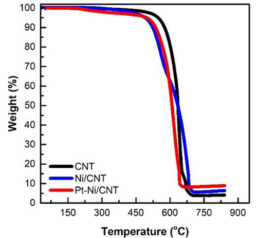
Fig. 1
Thermograms of CNT, Ni/CNT, and Pt-Ni/CNT materials.
Summary of metallic loading obtained by TGA for Pt-Ni/CNT in each stage of the synthesis.
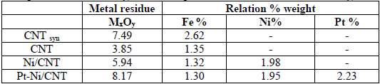
Once the Pt and Ni presence was identified, the particles' morphology was analyzed by microscopy, as shown in Fig. 2. The micrograph of Ni particles deposited on the CNT is shown in Fig. 2a); in the micrographs, CNT's characteristic tubular structure and small metal particles are deposited on CNT. However, the distribution of Ni particles on CNT was not evident in the micrographs. Therefore, the elemental mapping analysis was performed, as shown in Fig. 2b). Based on map analysis, the uniform scattered distribution of Ni particles can be appreciated
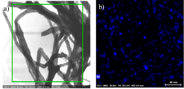
Fig. 2
Ni/CNT template a) FE-SEM image and b) Ni EDS mapping.
The Pt-Ni/CNT samples micrograph shown in Figure 3a; reveals the Ni and Pt metals deposited on carbon nanotubes. Fig. 3b) shows the elemental mapping, which confirms Pt and Ni metals evenly distributed throughout the CNT surface. The bimetallic particles are homogeneously distributed on CNT, as shown in Figures 3c) and 3d), respectively.
Fig. 3
Pt-Ni/CNT electrocatalyst a) FE-SEM image, b) EDS mapping of Ni and Pt, c) elemental mapping of Ni, and d) elemental mapping of Pt.
Electrocatalyst performance of Pt-Ni/CNT sample in the PEMFC
Fig. 4 shows Ni electrochemical dealloying in Pt-Ni/CNT sample to prepare the cathodic catalyst for the PEMFC test, applying different potential cycles (0, 170, and 1000 cycles). The Pt-Ni/CNT samples cyclic voltammograms show variations in the current of hydrogen adsorption/desorption zone for Pt surface between -0.2 to 0.6 V vs. RHE. In the anodic peak corresponding to hydrogen desorption from Pt surface, can be observed the current increases with the number of potential cycles, so this effect can be explained by the Pt-Ni/CNT catalyst surface restructuring, due to Ni atoms dealloying by the H2SO4 electrolyte during the potential cycling process, as reported in the literature previously [34].
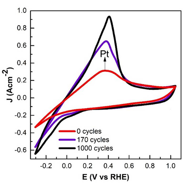
Fig. 4
Cyclic voltammogram of Pt-Ni/CNT electrocatalyst dealloying.
The hydrogen desorption charge consumption (QH) by Pt-Ni/CNT catalyst at the different potential cycles is summarized in Table 2. The QH increases with increasing potential cycle number, confirming Ni atoms dealloying and forming a Pt-layer on the Pt-Ni/CNT catalyst surface as previously reported by Glüsen et al. Pt can explain this behavior as the active phase for hydrogen adsorption/desorption process. The ECSA also evaluated in the hydrogen zone followed the same trend to respect potential cycles [35,36].
Electrochemical data of the Pt-Ni/CNT electrocatalyst with different activation cycles.
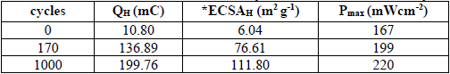
After Nickel atoms were dealloyed from Pt-Ni/CNT catalyst surface by different potential cycles, the fuel cell's catalytic performance was evaluated. Fig. 5 shows the polarization curve at 60 °C using Pt-Ni/CNT electrocatalyst at different potential cycles to increase Pt-layer surface and can be observed the typically open circuit and activation losses.
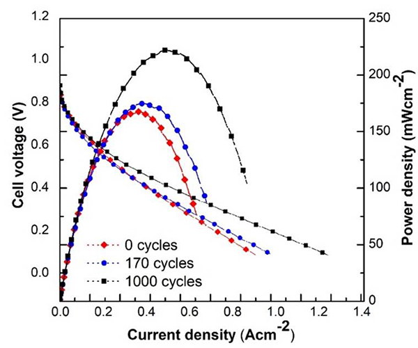
Fig. 5
Polarization curves of cathodic Pt-Ni/CNT electrocatalyst at different potential cycles.
The Pt-Ni/CNT at 0 potential cycles show the lowest loss in polarization voltage in accordance with QH and ECSA values reported in Table 2. The results of Pt-Ni/CNT electrocatalyst at 0 potential cycles indicate that the electrocatalyst surface show a low concentration of Pt, compared with the Pt-Ni/CNT at 1000 potential cycles. The Pt-Ni/CNT at 1000 potential cycles shows the maximum power density of 220 mW cm-2, confirming the Pt-layers were increasing over the Pt-Ni/CNT electrocatalyst surface by the electrochemical restructuration by potential cycles. Some authors report that the dealloying and leaching of less noble metal of bimetallic electrocatalyst can generate a porous structure by the migration of Ni atoms to the particle inside when the synthesis method generates core-shell particles by the galvanic displacement method [23,34,37,38]. Therefore, the fuel cell improvement in power density with Pt-Ni/CNT cathodic catalyst is attributed to Ni atoms dealloying to the H2SO4 electrolyte solution; and the enrichment of the electrocatalyst surface with a Pt-layer [39].
The Pt-Ni/CNT electrocatalysts catalytic performance was compared with Pt/C electrocatalyst at 1000 potential cycles both, as shown in Fig. 6. The polarization curve shows that Pt/C electrocatalyst produces the maximum power density of 350 mW cm-2 20wt% metallic content of pure platinum.
Fig. 6
Comparison of the polarization curves of Pt-Ni/CNT and commercial Pt/C at 1000 potential cycles.
The results indicate that the Pt-Ni/CNT electrocatalyst produces a 63% power density of the commercial Pt/C electrocatalyst with 90wt% fewer metal contents than reports in the literature. Lin et al. reported the catalytic performance of Pt1Ni1/C electrocatalyst with 30%wt metallic content, with a power density of 369.7 mW cm-2, very similar to a Pt/C commercial electrocatalyst. However, an evident decline in the catalytic activity after 1000 cycles was observed to 288 mW cm-2 [40]. Literature results indicate that high metallic contents poison the MEA of the PEMFC, reducing the catalytic performance because the dealloyed metal can be deposited in the MEA surface, blocking fuel diffusion. In Table 3 the power density generated before and after potential cycles of Pt-Ni electrocatalyst in the PEMFC are compared, normalized with respect to the Pt amount are reported.
Summary of the reported normalized power density with the amount of Pt.
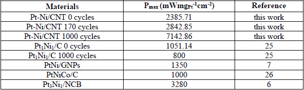
The ultra-low concentration of Pt and Ni metals in the Pt-Ni/CNT electrocatalyst does not affect the MEA performance with potential cycles than Lin et al. reported, as shown in Table 3. The synthesized Pt-Ni/CNT electrocatalyst with ultra-low Pt and Ni contents generated 8.93 times more power density at 1000 potential cycles compared to similar electrocatalysts with high metallic contents
Electrochemical characterization
The most popular methods to assess the ECSA are the underpotential deposition of hydrogen (Hupd) and CO stripping voltammetry in a three-electrode system [41,42]. The study of Hupd and CO stripping at differents potential cycles for Pt-Ni/CNT electrocatalyst are shown in Fig. 7. The black lines voltammograms show the Hupd region between 0 to 0.26 V vs. RHE as a sharp peak, attributed to the hydrogen adsorption/desorption process. The blue line voltammograms evaluate the surface properties of Pt-Ni/CNT electrocatalyst by the CO electrochemical oxidation. The region between 0.73 to 1.00 V vs. RHE shows the anodic peak, attributed to the adsorbed CO oxidation [43,44].
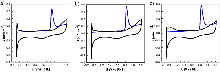
Fig. 7
Pt-Ni/CNT electrocatalyst CO stripping voltammogram at 0 (a), 170 (b), and 1000 (c) at 50 mV s-1 in H2SO4 0.5 M. Black-line (CO absence) and blue-line (CO presence).
ECSA-H values were calculated from the hydrogen desorption charge in the potential region from 0 to 0.26 V vs. RHE using the equation (1), and ECSA-CO values were calculated from the charge associated with CO oxidation in the potential region from 0.73 to 1.00 V vs. RHE using the equation (2). Where QH is the charge in mC determined by integration of hydrogen desorption region, QCO is the charge in mC determined by integration of CO oxidation peak, 0.210 mC cm-2 corresponds to hydrogen adsorption/desorption on polycrystalline Pt, 0.420 mC cm-2 corresponds to a monolayer of CO adsorbed and LPt. The Pt loading on the surface determined by ICP-IOS and TGA is seen in Table 1 [45]. Furthermore, the ratio between the ECSAs can be calculated, as shown in equation 3 [46].
 (1)
(1)
 (2)
(2)
 (3)
(3)The ESCA results of Pt-Ni/CNT electrocatalyst at different potential cycles are shown in Table 4. The calculated ECSA-H and ECSA-CO, and ECSA-H ratio, the Pt-Ni/CNT wat 0, 170, and 1000 activation cycles were 3.58, 3.25, and 1.58, respectively, where values greater than 1.5 of ECSAs ratio suggest forming a Pt-skin-terminated of Pt(111) as surface structure [13,17,47].
ECSAs of the Pt-Ni/CNT electrocatalyst at different activation cycles.
The electrochemical characterization shows the effect of potential cycles over ECSA of Pt-Ni/CNT determined by Hupd and CO stripping and corroborated MEA results in the PEMFC, where the electrochemical dealloying modified Pt-Ni/CNT electrochemical surface, increasing the Pt-layer exposure in catalyst surfaces, explaining the increase of the ECSA [34].
Conclusion
In this work, the Pt-Ni/CNT material was successfully synthesized for use as a cathodic electrocatalyst in PEM fuel cell technology. The performance of this electrocatalyst was improved with potential cycles. This, mainly due to the Pt surface restructuration by Ni atoms lixiviation. The Pt surface restructuration promotes that the ECSA increases with the number of potential cycles and suggests the optimization of Pt electrocatalysts sites; this is observed both in the cell in solution and in the fuel cell assembly. The maximum power density obtained for Pt-Ni/CNT with 1000 potential cycles was lower than shown by the commercial catalyst Pt/C, however, with an ultra-low amount of platinum present in the bimetallic catalyst (about 2%) compared to the 20% content of Pt in the commercial catalyst. However, with a better power generation per gram of platinum, reducing the cost of energy generation.
Acknowledgements
The authors thank Tijuana Technological Institute for providing the facilities for this research. D. M. Lopez-Rosas wishes to thank CONACyT for the doctoral scholarship. The authors also thank CONACyT-SENER and TecNM for financial assistance through the projects 292862 and 8080.20-P, respectively.
References
1. Meyer, Q.; Zeng, Y.; Zhao, C. Adv. Mater. 2019, 31 (40), 1901900 DOI: https://doi.org/10.1002/adma.201901900
2. Wang, L.; Wan, X.; Liu, S.; Xu, L. Shui, J. J. Energy Chem. 2019, 39, 77-87 DOI: https://doi.org/10.1016/j.jechem.2018.12.019
3. Singh, K.; Tetteh, E. B.; Lee, H.-Y.; Kang, T.-H.; Yu, J.-S. ACS Catal. 2019, 9 (9), 8622-8645 DOI: https://doi.org/10.1021/acscatal.9b01420
4. Safo, I. A.; Dosche, C.; Özaslan, M. Chemphyschem. 2019, 20 (22), 3010-3023 DOI: https://doi.org/10.1002/cphc.201900653
5. Beermann, V.; Holtz, M. E.; Padgett, E.; de Araujo, J. F.; Muller, D. A.; Strasser, P. Energy Environ. Sci. 2019, 12 (8), 2476-2485 DOI: https://doi.org/10.1039/C9EE01185D
6. Yang, H.; Ko, Y.; Lee, W.; Züttel, A.; Kim, W. Mater. Today Energy 2019, 13, 374-381 DOI: https://doi.org/10.1016/j.mtener.2019.06.007
7. Daş, E.; Alkan Gürsel, S.; Bayrakçeken Yurtcan, A. J. Supercrit. Fluids 2020, 165, 104962 DOI: https://doi.org/10.1016/j.supflu.2020.104962
8. Sudirman, S.; Adi, W.; Budianto, E.; Khaerudini, D.; Yudianti, R. Int. J. of Chem. 2019, 12, 37 DOI: https://doi.org/10.5539/ijc.v12n1p37
9. Liu, Z.; Abdelhafiz, A. A.; Jiang, Y.; Qu, C.; Chang, I.; Zeng, J.; Liao, S.; Alamgir, F. M. Mater. Chem. Phys. 2019, 225, 371-378 DOI: https://doi.org/10.1016/j.matchemphys.2018.12.100
10. Daş, E.; Kaplan, B. Y.; Gürsel, S. A.; Yurtcan, A. B. Renew. Energy 2019, 139, 1099-1110 DOI: https://doi.org/10.1016/j.renene.2019.02.137
11. Guzman, C.; Verde, Y.; Bustos, E.; Manriquez, F.; Terol, I.; Arriaga, L. G.; Orozco, G. ECS Trans. 2019, 20 (1), 413-423 DOI: https://doi.org/10.1149/1.3268409
12. Bharti, A.; Cheruvally, G. J. Power Sources 2017, 360, 196-205 DOI: https://doi.org/10.1016/j.jpowsour.2017.05.117
13. Chen, C.; Kang, Y.; Huo, Z.; Zhu, Z.; Huang, W.; Xin, H. L.; Snyder, J. D.; Li, D.; Herron, J. A.; Mavrikakis, M.; Chi, M.; More, K. L.; Li, Y.; Markovic, N. M.; Somorjai, G. A.; Yang, P.; Stamenkovic, V. R. Sci. 2014, 343 (6177), 1339-1343 DOI: https://doi.org/10.1126/science.1249061
14. Wang, Z.; Yao, X.; Kang, Y.; Miao, L.; Xia, D.; Gan, L. Adv. Funct. Mater. 2019, 29 (35), 1902987 DOI: https://doi.org/10.1002/adfm.201902987
15. Singh, K.; Tetteh, E. B.; Lee, H.-Y.; Kang, T.-H.; Yu, J.-S. ACS Catal. 2019, 9 (9), 8622-8645 DOI: https://doi.org/10.1021/acscatal.9b01420
16. Gan, L.; Heggen, M.; Rudi, S.; Strasser, P. Nano Lett. 2012, 12 (10), 5423-5430 DOI: https://doi.org/10.1021/nl302995z
17. Becknell, N.; Kang, Y.; Chen, C.; Resasco, J.; Kornienko, N.; Guo, J.; Markovic, N. M.; Somorjai, G. A.; Stamenkovic, V. R.; Yang, P. J. Am. Chem. Soc. 2015, 137 (50), 15817-15824 DOI: https://doi.org/10.1021/jacs.5b09639
18. Ghosh Chaudhuri, R.; Paria, S. Chem. Rev. 2012, 112 (4), 2373-2433 DOI: https://doi.org/10.1021/cr100449n
19. Alia, S. M.; Yan, Y. S.; Pivovar, B. S. Catal. Sci. Technol. 2014, 4 (10), 3589-3600 DOI: https://doi.org/10.1039/C4CY00736K
20. Ercolano, G.; Farina, F.; Stievano, L.; Jones, D. J.; Rozière, J.; Cavaliere, S. Catal. Sci. Technol. 2019, 9 (24), 6920-6928 DOI: https://doi.org/10.1039/C9CY01514K
21. Kang, Y. S.; Jung, J. Y.; Choi, D.; Sohn, Y.; Lee, S.-H.; Lee, K.-S.; Kim, N. D.; Kim, P.; Yoo, S. J. ACS Appl. Mater. Interfaces 2020, 12 (14), 16286-16297 DOI: https://doi.org/10.1021/acsami.9b22615
22. Oezaslan, M.; Hasché, F.; Strasser, P. J. Phys. Chem. Lett. 2013, 4 (19), 3273-3291 DOI: https://doi.org/10.1021/jz4014135
23. Tian, X.; Zhao, X.; Su, Y.-Q.; Wang, L.; Wang, H.; Dang, D.; Chi, B.; Liu, H.; Hensen, E. J. M.; Lou, X. W.; Xia, B. Y. Science 2019, 366 (6467), 850-856 DOI: https://doi.org/10.1126/science.aaw7493
24. Pavlišič, A.; Jovanovič, P.; Šelih, V. S.; Šala, M.; Bele, M.; Dražić, G.; Arčon, I.; Hočevar, S.; Kokalj, A.; Hodnik, N.; Gaberšček, M. ACS Catal. 2016, 6 (8), 5530-5534 DOI: https://doi.org/10.1021/acscatal.6b00557
25. Ho, F. F. L.; Reilley, C. N. Anal. Chem. 1969, 41 (13), 1835-1841 DOI: https://doi.org/10.1021/ac60282a008
26. De Stefano, C.; Foti, C.; Sammartano, S. J. Chem. Eng. Data 1999, 44 (4), 744-749 DOI: https://doi.org/10.1021/je980319n
27. Yang, Y.; Li, S.; Xie, C.; Liu, H.; Wang, Y.; Mei, Q.; Liu, H.; Han, B. Chin. Chem. Lett. 2019, 30 (1), 203-206 DOI: https://doi.org/10.1016/j.cclet.2018.04.006
28. Zhang, L.; Chu, X.; Yuan, S.-m.; Zhao, G.-c. RSC Adv. 2015, 5 (52), 41317-41323 DOI: https://doi.org/10.1039/C5RA03306C
29. Watkins, C. L.; Vigee, G. S. J. Phys. Chem. A 1976, 80 (1), 83-88 DOI: https://doi.org/10.1021/j100542a018
30. Tsierkezos, N.; Schröder, D.; Schwarz, H. Int. J. Mass Spectrom 2004, 235, 33-42 DOI: https://doi.org/10.1016/j.ijms.2004.03.005
31. Reyes-Cruzaley, A. P.; Félix-Navarro, R. M.; Trujillo-Navarrete, B.; Silva-Carrillo, C.; Zapata-Fernández, J. R.; Romo-Herrera, J. M.; Contreras, O. E.; Reynoso-Soto, E. A. Electrochim. Acta 2019, 296, 575-581 DOI: https://doi.org/10.1016/j.electacta.2018.11.023
32. Osorio, A. G.; Silveira, I. C. L.; Bueno, V. L.; Bergmann, C. P. Appl. Surf. Sci. 2008, 255 (5, Part 1), 2485-2489 DOI: https://doi.org/10.1016/j.apsusc.2008.07.144
33. Rodriguez, J. R.; Félix, R. M.; Reynoso, E. A.; Gochi-Ponce, Y.; Gómez, Y. V.; Moyado, S. F.; Alonso-Núñez, G. J. Energy Chem. 2014, 23 (4), 483-490 DOI: https://doi.org/10.1016/S2095-4956(14)60175-3
34. Baldizzone, C.; Gan, L.; Hodnik, N.; Keeley, G. P.; Kostka, A.; Heggen, M.; Strasser, P.; Mayrhofer, K. J. J. ACS Catal. 2015, 5 (9), 5000-5007 DOI: https://doi.org/10.1021/acscatal.5b01151
35. Glüsen, A.; Dionigi, F.; Paciok, P.; Heggen, M.; Müller, M.; Gan, L.; Strasser, P.; Dunin-Borkowski, R. E.; Stolten, D. ACS Catal. 2019, 9 (5), 3764-3772 DOI: https://doi.org/10.1021/acscatal.8b04883
36. Erlebacher, J. Phys. Rev. Lett. 2011, 106 (22), 225504 DOI: https://doi.org/10.1103/PhysRevLett.106.225504
37. Wang, D.; Zhao, P.; Li, Y. Sci. rep. 2011, 1, 37 DOI: https://doi.org/10.1038/srep00037
38. Rudi, S.; Gan, L.; Cui, C.; Gliech, M.; Strasser, P. J. Electrochem. Soc. 2015, 162 (4), F403-F409 DOI: https://doi.org/10.1149/2.0621504jes
39. Tuaev, X.; Rudi, S.; Petkov, V.; Hoell, A.; Strasser, P. ACS Nano 2013, 7 (7), 5666-5674 DOI: https://doi.org/10.1021/nn402406k
40. Lin, R.; Che, L.; Shen, D.; Cai, X. Electrochim. Acta 2020, 330, 135251 DOI: https://doi.org/10.1016/j.electacta.2019.135251
41. Rudi, S.; Cui, C.-H.; Gan, L.; Strasser, P. Electrocatalysis 2014, 5, 408-418 DOI: https://doi.org/10.1007/s12678-014-0205-2
42. Urchaga, P.; Baranton, S.; Coutanceau, C. Electrochim. Acta 2013, 92, 438-445 DOI: https://doi.org/10.1016/j.electacta.2013.01.042
43. Takeshita, T.; Kamitaka, Y.; Shinozaki, K.; Kodama, K.; Morimoto, Y. J. Electroanal. Chem. 2020, 871, 114250 DOI: https://doi.org/10.1016/j.jelechem.2020.114250
44. Rudi, S.; Teschner, D.; Beermann, V.; Hetaba, W.; Gan, L.; Cui, C.; Gliech, M.; Schlögl, R.; Strasser, P. ACS Catal. 2017, 7 (9), 6376-6384 DOI: https://doi.org/10.1021/acscatal.7b00996
45. Vidaković, T.; Christov, M.; Sundmacher, K. Electrochim. Acta 2007, 52 (18), 5606-5613 DOI: https://doi.org/10.1016/j.electacta.2006.12.057
46. Becknell, N.; Son, Y.; Kim, D.; Li, D.; Yu, Y.; Niu, Z.; Lei, T.; Sneed, B. T.; More, K. L.; Markovic, N. M.; Stamenkovic, V. R.; Yang, P. J. Am. Chem. Soc. 2017, 139 (34), 11678-11681 DOI: https://doi.org/10.1021/jacs.7b05584
47. van der Vliet, D. F.; Wang, C.; Li, D.; Paulikas, A. P.; Greeley, J.; Rankin, R. B.; Strmcnik, D.; Tripkovic, D.; Markovic, N. M.; Stamenkovic, V. R. Angew. Chem. Int. Ed. 2012, 51 (13), 3139-3142 DOI: https://doi.org/10.1002/anie.201107668
Author notes
*Corresponding author: E.A. Reynoso-Soto, email: [email protected]
